- Products
-
- VSD Wiki
- Contact us

VSD manufacturers
sales@VariableSpeedDrive.co.za
Home » FAQ
 Variable speed drive shall be used where speed variation is a process requirement or it results in energy saving. This has to be decided based on application requirements. During my 24 year experience of designing variable speed drive motors for various applications all over the world I have come across very few users who simply use variable speed drive for fashion without knowing the implications. While designing variable speed drive motors one has to understand the applications to do full justice.
Most variable speed drive manufacturers require a reference to the neutral point of the winding, particularly for larger equipment. This connection serves as their primary "check" for unbalance in phase-phase and phase-ground circuits. As a side benefit, it keeps the VSD from accidentally damaging the machine winding insulation by over-voltaging the terminals by keeping the VSD and motor neutral at the same value.
In selecting a variable speed drive, consideration must be given to the load characteristics of the driven machinery. The three basic load categories can be summarized as follows:
- Constant-torque loads require a constant motor torque throughout the operational speed range.
- Loads of these types are essentially friction loads such as traction drives & conveyors.
- Variable-torque loads require much lower torque at low speeds than at high speeds. Loads that exhibit variable torque characteristics include centrifugal fans, pumps, & blowers.
- Shock (impact) loads require a motor to operate at normal load conditions followed by a sudden, large load applied to the motor. An example would be the sudden shock load that results from engaging a clutch that applies a large load to the motor (as it would during a hard start). This current spike could cause the variable speed drive to trip as a result an excessive motor current fault.
Here is the QUIZ about variable speed drives:
1. List the common basic control function of an electronic variable speed drive.
2. What is the preferred method for altering the speed of a squirrel-cage induction motor?
3. State the prime function of each of the following parts of a variable speed drive: (a) converter, (b) DC bus, (c) inverter, (d) control logic.
4. Explain how it's possible for a variable speed drive to operate a three-phase motor from a single phase power source.
5. Calculate the average DC bus voltage for a line volt age of 230 V AC.
6. Which component is the main energy storage element of the DC bus?
7. What types of transistor are currently used in the inverter section of a variable speed drive?
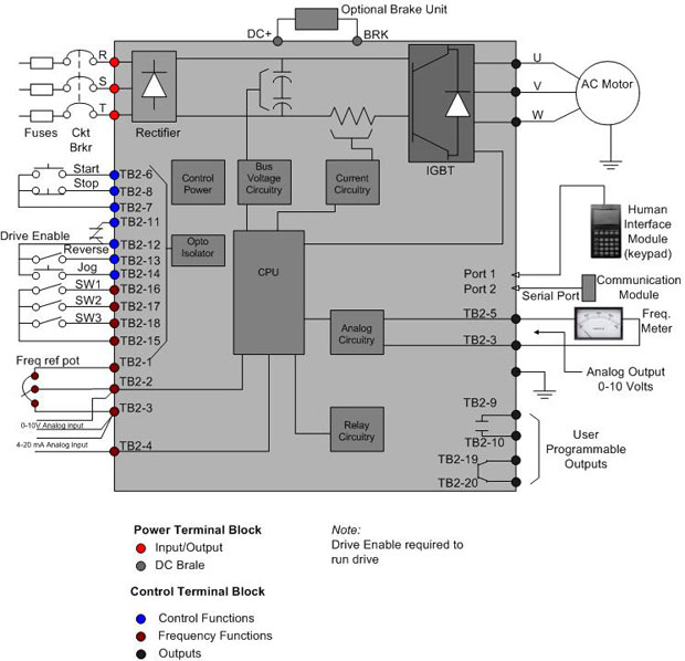
A variable speed drive controls the speed, torque, & direction of an AC induction motor. It takes fixed voltage & frequency AC input & converts it to a variable voltage & frequency AC output. Below Fig shows the block diagram of a typical three phase variable speed drive controller.

The function of each block is as follows:

The function of each block is as follows:
- Converter: A full-wave rectifier that converts the applied AC to DC.
- DC bus: Also referred to as a DC link, connects the rectifier output to the input of the inverter. The DC bus functions as a filter to smooth the uneven, rippled output to ensure that the rectified output resembles as closely as possible pure DC.
- Inverter: The inverter takes the filtered DC from the DC bus & converts it into a pulsating DC waveform. By controlling the output of the inverter, the pulsating DC waveform can simulate an AC waveform at different frequencies.
- Control logic: The control logic system generates the necessary pulses used to control the firing of the power semiconductor devices such as SCRs & transistors. Fairly involved control circuitry coordinates the switching of power devices, typically through a control board that dictates the firing of power components in the proper sequence. An embedded microprocessor is used for all internal logic & decision requirements.
Proper speed control means that you need to vary both the motor voltage and frequency to control slip and keep it in a sweet zone in relation to the actual rotation speed. This is what Variable Speed Drives do. A fly in the ointment however is that for single phase induction motors this idea does not really work. You noted that i wrote earlier that the stator windings create a rotating magnetic field. Only you won't get rotation with just one phase, you get a pulsing voltage only. For this reason single phase motors artificially create a second phase to create the rotation. This second phase can be created in many ways using auxiliary windings and phase shift capacitors or coils. Combining a variable speed drive and a single phase motor is at best a horrible kludge and usually does not even begin to work. All proper variable speed drive controlled induction motors are 3 phase, as are the outputs of the variable speed drives. 3 phase shifted voltages is the minimum required to create a rotating field.
Back to single phase motors. In certain kinds of application, you can skip variable speed drives and simply control the motor by controlling the effective stator voltage using a triac or thyristor or whatever. This does nothing to the supply frequency, which is the standard 50/60 Hz all the time. So what is controlled is the amount of slip, by crude indirect torque control by stator voltage. If the load curve is monotonously increasing and sufficiently steep, the rotation speed will follow the stator voltage. Not linearly and not with world class dynamics, but it will follow. Now it happens that a fan is typically this kind of load and for that reason this simple scheme works quite OK for most fans.
Back to single phase motors. In certain kinds of application, you can skip variable speed drives and simply control the motor by controlling the effective stator voltage using a triac or thyristor or whatever. This does nothing to the supply frequency, which is the standard 50/60 Hz all the time. So what is controlled is the amount of slip, by crude indirect torque control by stator voltage. If the load curve is monotonously increasing and sufficiently steep, the rotation speed will follow the stator voltage. Not linearly and not with world class dynamics, but it will follow. Now it happens that a fan is typically this kind of load and for that reason this simple scheme works quite OK for most fans.
In answer to "one- or two-variable speed drive solution", I have to say: What is it you are trying to accomplish?
If all you want to do is load your variable speed drive/motor combination to 100% (or higher), the single variable speed drive solution will cost you the least in materials and will allow you to achieve your goal. If you need to load the motor/variable speed drive combination over a wide speed range, you need two variable speed drives. If you can get an identical motor and variable speed drive, and the variable speed drive manufacturer OK's the common-bus solution proposed above would be the least-cost option for that scenario.
If common-bus is not an option, the load variable speed drive sizing will be dependent on how much braking power the load variable speed drive will absorb over the duration you need it to. My application required 100% load for fifteen minute periods. Toshiba advised that a 37kW variable speed drive I had available could absorb 13kW in regen power continuously using their standard heavy-duty dynamic braking resistor. They also recommend that the motor connected to their variable speed drive not be less than 50% of the variable speed drive rating. I had a 30kW motor available of the same nameplate speed as the test motor, so that's what I went with. Testing proved that 15kW was all the 37kW variable speed drive would absorb. If I tried to regen above that, the variable speed drive would not accept a lower speed reference because the DC buss voltage could not be brought down by the DB resistor circuit.
