- Products
-
- VSD Wiki
- Contact us

VSD manufacturers
sales@VariableSpeedDrive.co.za
Home » Application
Our cooling tower pumps are fixed speed but we have variable speed drives on the cooling tower fans. These do a good job of controlling the cooling tower supply temperature except in those installations where the cooling tower sump size is excessive (China). With the flow control valves on the individual exchanges, the variable speed drive may not be absolutely necessary, but the process temperature control works better if it doesn't have to deal with daytime to nighttime or storm induced variation in supply temperature.
Controlling pumps by variable speed drive improves production and site environment, and meet technics requirement completely. Integration of PLC control, Profibus technology and medium voltage variable speed drive leads to high automatization level, stable operation, easy operation and considerable energy saving.
Successful application of variable speed drive in Shenzhen Third Water Plant has enormous economic value in energy saving, technology innovation and downsize staff for high efficiency.
Successful application of variable speed drive in Shenzhen Third Water Plant has enormous economic value in energy saving, technology innovation and downsize staff for high efficiency.
At present, competition is very intense. The key is cost. Power consumption of motor accounts for 30% of cost. Motor driving fan is a big part. So it is very important to reduce consumption of motor. Today, phenomenon of "large horse drives small dolly" is serious. If technology of variable speed is adopted, it not only satisfies production requirement but also saves energy. Meanwhile, variable speed drive saves a lot of energy source and improves efficiency for plant. After innovation with variable speed drive, energy saving rate is in 30-50%. The investment usually recovers in one or two years.
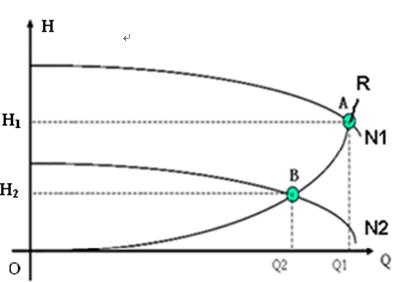
If 100% speed -100% flow -100% pressure-100% output power,there is: 80% speed- 80%flow- 64% pressure- 51% output power. Namely, in variable speed state, when flow reduces 20%, shaft power reduces 49%. That is the reason why variable speed drive has a considerable energy saving effect.

If 100% speed -100% flow -100% pressure-100% output power,there is: 80% speed- 80%flow- 64% pressure- 51% output power. Namely, in variable speed state, when flow reduces 20%, shaft power reduces 49%. That is the reason why variable speed drive has a considerable energy saving effect.
This article aimed to evaluate the uniformity of distribution and water depth applied with a center pivot irrigation systems according to the change in speed of rotation of set irrigation motor pump with a variable speed drive and the effect of the position of the lateral line in these parameters. Three positions of lines of collecting water were tested: incline of 3.45%, level and slope of 11.78%. The experimental design was completely randomized, with three replications made at each position tested. Analysis of variance was applied followed by Tukey test. Thee average value of the coefficient of uniformity of Heermann e Hein was 88.85%, describing the uniformity of water distribution as good. The mean weighed depth of irrigation applied was 5.71 mm, varying significantly within each test (5%) between the positions of slope versus incline and level. It was concluded that the position of the lateral line influenced significantly in the rotation of the set irrigation pump by variable speed drive, water depth applied and energy consumption. However, in the values of uniformity of water distribution there was no difference.
Variable speed drive sets speeds of 5 stages according to above table and speeds are required to be adjusted. Lowest speed of fan is set 10Hz temporarily and it is variable speed drive acceleration time is 46s (0~50Hz), no requirement for deceleration time. Variable speed drive should meet requirement of accelerating during deceleration.
Metal mixer of the steel plant uses a variable speed drive to control speed. The variable speed drive is high-high voltage source drive. Its main data is following: capacity is 1050KVA, rated output current is 105A, input frequency 45Hz~55Hz, rated input voltage 6000V, allowable voltage vibration -10%~10%, input power factor ≥0.96, output frequency 0~50Hz (speed adjustment range 0~100%), variable speed drive efficiency ≥98% (not including transformer), frequency resolution is 0.01Hz, stepless speed adjustment, overload capacity: 120% for 1min and 150% immediately. Acceleration time and deceleration time are set as per technics requirement.
Metal mixer of the steel plant uses a variable speed drive to control speed. The variable speed drive is high-high voltage source drive. Its main data is following: capacity is 1050KVA, rated output current is 105A, input frequency 45Hz~55Hz, rated input voltage 6000V, allowable voltage vibration -10%~10%, input power factor ≥0.96, output frequency 0~50Hz (speed adjustment range 0~100%), variable speed drive efficiency ≥98% (not including transformer), frequency resolution is 0.01Hz, stepless speed adjustment, overload capacity: 120% for 1min and 150% immediately. Acceleration time and deceleration time are set as per technics requirement.
Hoist machine is one of the most power-consuming and important equipments in mine. Its reliability influences production and personnel safety directly. Meanwhile, speed adjustment mode of Hoist machine is also a big factor for power consumption.
For long term, Hoist machine adopts rotor series resistance to adjust speed. It is low cost but with big torque, high consumption and complicated circuit. It damages contactor, resistor and electrical brush easily, which threatens system safety. With rapid development of power and motor technology, variable speed technology can solve above problems.
Operation performance of variable speed adjustment
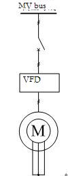
Short connect rotor winding of motor, convert power frequency voltage to voltage of some frequency through electrical components inside variable speed drive and the voltage is applied to stator winding of motor. It controls motor to run in expected speed by adjusting output voltage, frequency and phase position. Its circuit is shown following:
Compared with mode of rotor series resistance, variable speed technology has advantages of small current, stable motor operation, small torque pulsation, high controllability and energy saving.
Main control methods of variable speed technology are VVVF control, slip differential frequency control, direct torque control and vector control. vector control can realize decoupling control of magnetic flux and torque by modeling for motor, with the best control performance. Gozuk variable speed drive introduced in this paper adopts vector control. It is applicable for Hoist machine as its good control performance.
In vector control, variable speed drive can calculate magnetic-flux position, magnetic-flux amplitude, output torque and motor speed according to voltage signal, current signal, motor parameters and motor modeling. Then according to deviation of this speed and given speed, it adjusts output torque. If output torque is more than given "max torque", it outputs max torque.
For long term, Hoist machine adopts rotor series resistance to adjust speed. It is low cost but with big torque, high consumption and complicated circuit. It damages contactor, resistor and electrical brush easily, which threatens system safety. With rapid development of power and motor technology, variable speed technology can solve above problems.
Operation performance of variable speed adjustment
Short connect rotor winding of motor, convert power frequency voltage to voltage of some frequency through electrical components inside variable speed drive and the voltage is applied to stator winding of motor. It controls motor to run in expected speed by adjusting output voltage, frequency and phase position. Its circuit is shown following:

Compared with mode of rotor series resistance, variable speed technology has advantages of small current, stable motor operation, small torque pulsation, high controllability and energy saving.
Main control methods of variable speed technology are VVVF control, slip differential frequency control, direct torque control and vector control. vector control can realize decoupling control of magnetic flux and torque by modeling for motor, with the best control performance. Gozuk variable speed drive introduced in this paper adopts vector control. It is applicable for Hoist machine as its good control performance.
In vector control, variable speed drive can calculate magnetic-flux position, magnetic-flux amplitude, output torque and motor speed according to voltage signal, current signal, motor parameters and motor modeling. Then according to deviation of this speed and given speed, it adjusts output torque. If output torque is more than given "max torque", it outputs max torque.
Tags: Mining industry
There is a drain pipe of diameter 1000mm which is in gas lane of goaf bottom and comes to pump room. Pump is water ring vacuum pump. Please see technical diagram in following:

Here are parameters:
Pump parameters
Rated speed: 340r/min
Max drain flow: 635m3/min
Ultimate vacuum: 160MPa
Motor parameters
Rated power: 900kW
Rated voltage: 6kV
Rated current: 104.2A
Rated speed : 1483r/min
Power factor: 0.87

Here are parameters:
Pump parameters
Rated speed: 340r/min
Max drain flow: 635m3/min
Ultimate vacuum: 160MPa
Motor parameters
Rated power: 900kW
Rated voltage: 6kV
Rated current: 104.2A
Rated speed : 1483r/min
Power factor: 0.87
Tags: Mining industry
In order to fully ensure the system reliability, a bypass device is configured with the medium voltage variable speed drive. When the medium voltage variable speed drive operates abnormally, it will stop and the motor may be manually switched to be driven directly by the power supply. The bypass circuit is composed of 3 medium voltage disconnect switches QS1, QS2 and QS3 (see the fig.6 in which QF is the original medium voltage switch). It is required that QS2 and QS3 may not be closed simultaneously and they are interlocked mechanically. When the motor is driven by medium voltage variable speed drive, QS1 and QS2 are closed and QS3 is open; and when the motor is driven by the power, QS3 is closed and QS1 and QS2 are open.

Fig.6 bypass circuit
In order to protect from medium voltage variable speed drive failure, the variable speed drive is interlocked with the 6kV switch QF. Once medium voltage variable speed drive fails, medium voltage variable speed drive will make QF switched off. It is required that the user makes suitable reform to the switching circuit. When the bypass circuit is acted, medium voltage variable speed drive will allow QF switch-on and cancel the switch off signal to enable the motor to start with the power through QF switching on.
To ensure safe operation of the generator unit, the reserved cycling pump is required to operate automatically under the operation mode of single cycling pump with variable speed drive, when variable speed drive fails and QF switches off. To adapt the improvement of automation level of cycling pump system after reform with variable speed drive, the outlet water valve is also interlocked for automatic control. The function of the valve interlock is: During the pump starts and its speed increases, the pump outlet water pressure increases gradually, and when the pressure is greater than the "minimum outlet water pressure for opening valve", the valve begins to open until to open fully. When the pump stops, the valve will close simultaneously. If the valve opens not completely for various reasons when the pump starts, "valve not open fully" will be displayed. If the valve closes not completely when the pump stops, "valve not close fully" will be displayed. Thus, during starting and stopping the pump, the personnel on duty need not to perform any operation to the valve and thus, not only operation miss will decrease but also the shock to the pipe network during opening valve and closing valve will be very small.
The variable speed drive system is of voltage resource type and has features of stable operation, wide speed regulating range, good output waveform, low input current harmonic, high power factor and high effectiveness, etc. It has low harmonic contamination to the electric network. The total harmonic distortion THD is less than 4% and complies with the standard of harmonic suppression of IEEE519-1992 directly and input harmonic filters are not required to be used. It has high power factor and power factor correction capacitors are not required. It has good output waveform, without additional heating of motor, torque pulsing, noises, output dv/dt and common mode voltage, etc. caused by harmonic. Output filters are not necessary and common asynchronous motors can be used.
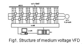
The variable speed drive uses topology structure of cells in series, multi-level PWM (in brief CSML). Direct high voltage output is implemented in the form of several low-voltage PWM variable frequency power cells in series.

The variable speed drive uses topology structure of cells in series, multi-level PWM (in brief CSML). Direct high voltage output is implemented in the form of several low-voltage PWM variable frequency power cells in series.
With multi-level cell-connection-in-series technology, medium voltage variable speed drive is composed of phase-shifting transformer, power cell and controller (For the configuration of the 6kV system, see Fig 1). The 6 kV series variable speed drive has 21 power cells and every 7 cells make up a phase in series.
All cells are identical in the structure and electrical parameters of and may be replaced each other. The circuit is basic AC-DC-AC single-phase variable speed drive circuit (See Fig 2). The rectifier is a three-phase diode bridge. Controlling the IGBT inverter by sinusoidal PWM way, the output voltage waveform is shown in fig 3.
Each secondary of the phase shifting transformer supplies power to a power cell. The transformer's secondaries are divided into three groups. For 6000V series, 42 pulses rectifier mode is formed. The multi-pulse overlap rectifier mode greatly improves the quality of the line current waveform, and the input power factor can be improved up to near 1.
In addition, the independence of the transformer's secondaries makes the power cells' main circuit relatively separate. The main circuit of the power cell is similar to the circuit of the low voltage variable speed drive.
At the output side, each cell's U terminal and the neighbor cell's V terminal are connected in series to form a three phase star (wye) connection to supply power for the motor. By overlapping each cell's PWM waveform, we can get the multi-level SPWM waveform shown in Fig. 4. It is a excellent sine-shape, small dv/dt, no cable and motor insulation destruction, no output filter for long output cable, no motor derating, and it can be used in driving the old motor directly. Meanwhile the motor harmonics are reduced greatly, the mechanical vibration is eliminated, and the mechanical stress of shaft and vanes is reduced.
All cells are identical in the structure and electrical parameters of and may be replaced each other. The circuit is basic AC-DC-AC single-phase variable speed drive circuit (See Fig 2). The rectifier is a three-phase diode bridge. Controlling the IGBT inverter by sinusoidal PWM way, the output voltage waveform is shown in fig 3.
 | |  |
| Fig.1 Structure of medium voltage variable speed drive | | Fig.2 Circuit of power cell |
Each secondary of the phase shifting transformer supplies power to a power cell. The transformer's secondaries are divided into three groups. For 6000V series, 42 pulses rectifier mode is formed. The multi-pulse overlap rectifier mode greatly improves the quality of the line current waveform, and the input power factor can be improved up to near 1.
In addition, the independence of the transformer's secondaries makes the power cells' main circuit relatively separate. The main circuit of the power cell is similar to the circuit of the low voltage variable speed drive.
At the output side, each cell's U terminal and the neighbor cell's V terminal are connected in series to form a three phase star (wye) connection to supply power for the motor. By overlapping each cell's PWM waveform, we can get the multi-level SPWM waveform shown in Fig. 4. It is a excellent sine-shape, small dv/dt, no cable and motor insulation destruction, no output filter for long output cable, no motor derating, and it can be used in driving the old motor directly. Meanwhile the motor harmonics are reduced greatly, the mechanical vibration is eliminated, and the mechanical stress of shaft and vanes is reduced.
Personnel adjusts output value of DCS according to temperature of flue gas, temperature of boiler vapour and negative pressure. This output value is given value of frequency (speed) which is 4~20mA signal feeding back to variable speed drive. Variable speed drive compares speed output and given value, then adjusts motor speed automatically.
On above base, draw curve of given value in different loads and temperatures. Fix safe up limitation and safe low limitation, make special arithmetic of fan speed adjustment. Send samples of load, temperature and negative pressure variety to DCS. DCS makes control operation, feeds back the outcome to variable speed drive in form of 4~20mA signal. variable speed drive adjusts speed automatically through comparing speed output and given value from DCS, thereby adjusting motor speed and implementing auto control of fan speed.
Here are characters of variable frequency speed adjustment system: speed adjustment system can run in variable frequency, and also can switch to direct on line. When control power of variable speed drive is off, inside UPS can supply power to maintain continuous operation. When speed given from DCS faults, variable speed drive alarms, meanwhile, variable speed drive continues to run in original speed and keeps working condition unchangeable. Preserve original motor, no need to change original equipment.
The whole system consists of PLC, variable speed drive, energy feedback system, electric motor, reduction box, AC input reactor, transformer, operation hand shank etc., to control the start, stop, up going, down going, brake and every kinds of protection of the elevator. The elevator will work at the condition of high-efficiency, safe and stable, meanwhile, the regenerated energy while the elevator going down will be fed back to the power grid to save energy.
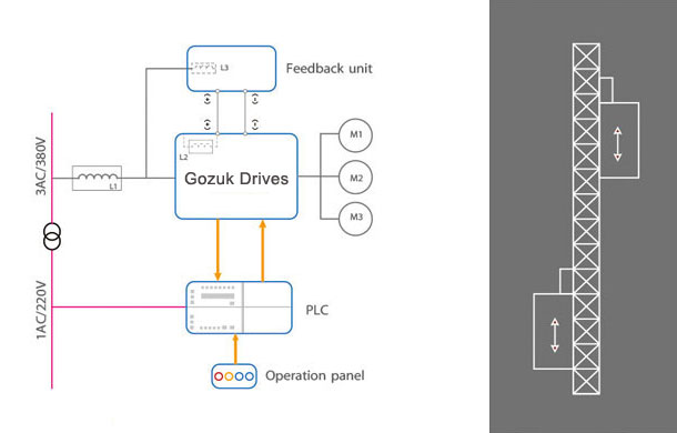
Advantage of the variable speed drive solution

Advantage of the variable speed drive solution
- High-efficiency, the running speed is as high as 60~70m/min which is double of traditional elevator(34 m/min);
- Energy feeds back to power grid, save considerable energy for customer, good braking effect;
- High output torque in low speed;
- Reduce the driving concussion of mechanism system effectively, prolong the working life of gear, contact roller, bearing and gear rack; The current limitation function of variable speed drive reduces the surge current while starting the motor, and also reduce the interference among the power consumption devices;
- The system has perfect safety protect functions such as under voltage, over voltage, over torque, over current and so on; it enhances the reliability and safety for the total system.
- The system adopts low-speed braking method, the small rotary friction force prolongs the working life of brake effectively.
- Compare with traditional non speed adjustable elevator, the comfortable feeling during operation is wonderful.
